Checkerboard Calibration
Checkerboard Calibration uses calibration plate to compute intrinsic parameters such as lens distortion and perspective distortion and generate images that are distortion free. After checkerboard calibration, a transform between Raw2D and Plate2D will be established. Checkerboard calibration targets are also used in other calibrations such as hybrid hand-eye calibration, hybrid cross calibration or hybrid manual calibration. In all these calibrations, the checkerboard is used to compute intrinsic parameters. The other calibration parameters are computed on the images that are free of these non-linear distortions.
Calibration plate
There are two major type of checkerboard plate used in AlignPlus.
-
Standard Calibration Plate
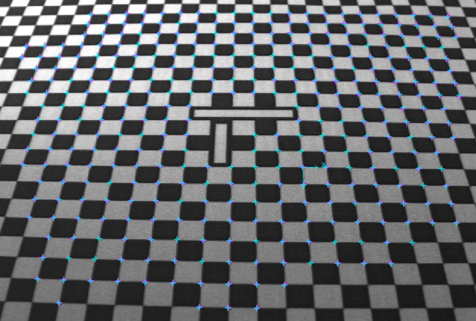
Standard calibration plate is a plate with intersective white and black tiles, every tile shares the same height and width. Typical pitch(the distance between successive corresponding points or lines) of different calibration plates are 0.5mm, 1mm, 2mm, 5mm and 10mm. The tiles provide references for vision on how real equal-distance points are distributed under the camera, thus help vision to calculate how much lens or perspective distortions the camera has.
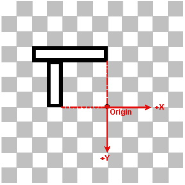
As for Plate2D definition, if the plate doesn't have any fiducial indicating x, y directions, then user needs to manually selecting x,y axes and origin on calibration image for Plate2D. However if a "L" shape fiducial is seen in FOV, then vision will automatically define Plate2D based on the L-shape fiducial(shown as below).
Without fiducial With fiducial 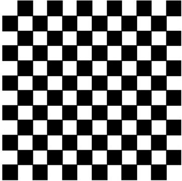
-
DataMatrix Calibration Plate
DataMatrix Calibration plate uses DataMatrix codes to label the locations of multiple grid vertices on the plate with unique Plate2D origin (each DataMatrix code has different coordinates).
Some DataMatrix code not only has coordinates information, but also indicates plate's grid pitch. Based on this, DataMatrix calibration plate are classified to two types:
-
DataMatrix without Grid Pitch
User need to input pitch on UI manually
-
DataMatrix with Grid Pitch
User doesn't need to input pitch, vision will automatically identify the pitch size by reading information from DataMatrix code.
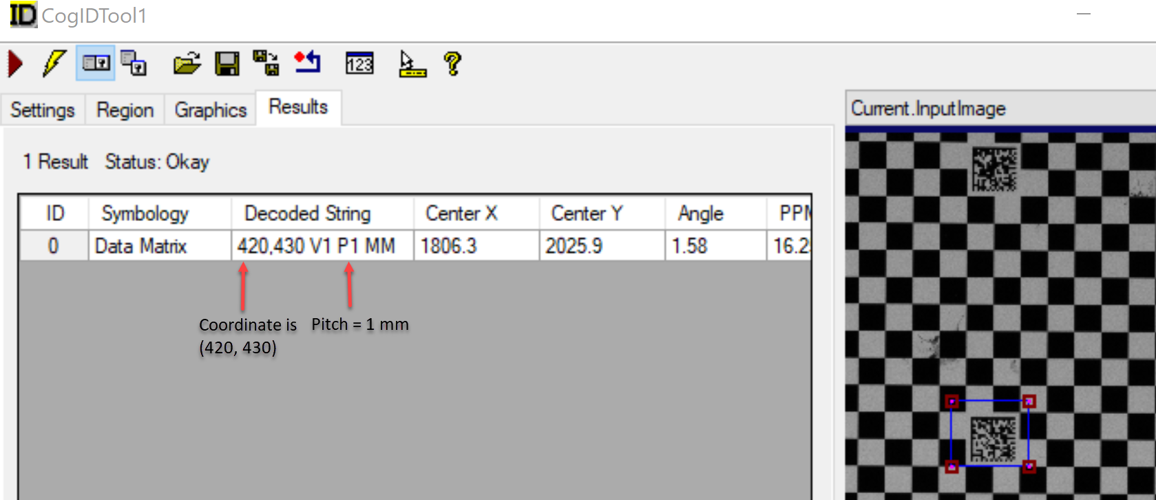
However, the two types have no difference in appearance to human eyes, the only difference is DataMatrix code content. To tell which type it is, user can run CogIDTool in VisionPro ToolBlock to get the content of it.
Here is an example of DataMatrix with Grid Pitch:
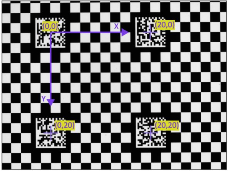
The following figure shows how multiple DataMatrix fiducial marks serve to label four vertices on a checkerboard calibration plate (in this case, a plate with a 2mm grid pitch)
-
For information about checkerboard vertex extraction and Plate2D definition, please refer to Feature Extractor.
Train Time
Checkerboard plate should be rigidly attached to an precision motion stage before hand. The checkerboard plate material could vary from stainless steel to pottery to transparent mylar sheet depending on applications. Mylar sheet is widely used as it's thin enough to be picked up by robot or gripper using vacuum, and it has two identical and transparent sides which can be easily transferred between upward surface and downward surface and captured by down-looking camera or up-looking camera.
Once the plate is in position, take a picture of the calibration plate, and run checkerboard calibration to get the calibration result.
For calibration best practice, it is recommended:
-
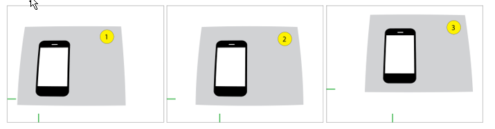
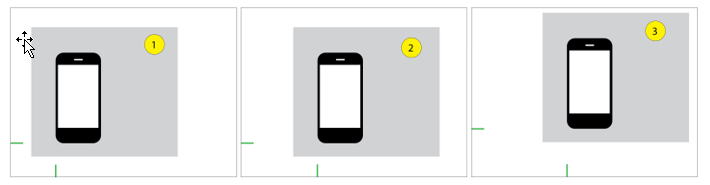
Calibration plate cover the whole FOV
-
Keep calibration plate flat
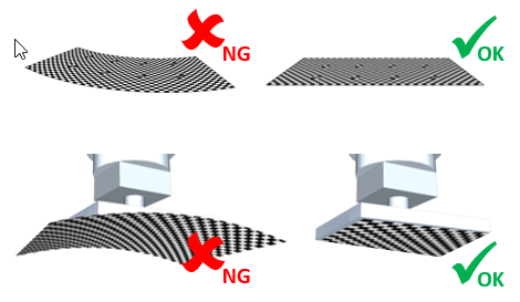
- Make sure calibration plate is within focus
- Keep plate clean so the coverts are extracted correctly
- Adjust lighting or exposure time to make white and black tiles have good contrast without oversaturation
Calibration Result Check
-
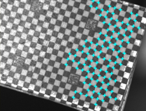
Feature extraction rate
It is recommended that over 70% of the checkers within FOV should be extracted. The calibration is accurate in areas with extracted checkers. In areas without checker features, the calibration is computed by extrapolation, which will result in low accuracy.
High extraction rate
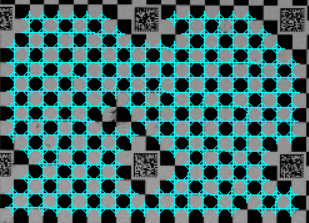
Low extraction rate
-
RMS
RMS(Root Mean Square) indicates checkerboard calibration result by comparing differences between uncalibrated points and raw calibrated points.
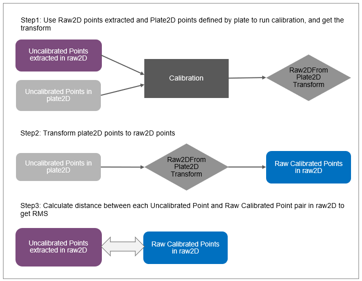
The diagram above shows how RMS error is computed during checkerboard calibration.
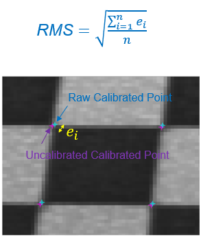
For high-accurate application, RMS error in Raw2D should be within 1 pixel.
Run Time
Checkerboard calibration computes intrinsic parameters such as lens and perspective distortion. They also generate image correctors that take the image captured by the camera as an input and generate images that are free of these distortions. Many of Cognex's vision tools assume that the relationship between Raw2D and Client2D is an affine transform. The correctors generate images for which this assumption holds true.
-
raw images
-
corrected images
User can also choose specific lens distortion mode for image correction depending on the lens type used in application, please refer to Lens Distortion Mode.